7 steps to successful aluminium brazing
Step 1
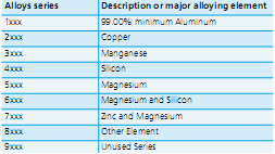
Select the Right Alloy at Controlled Atmosphere Conditions Aluminum alloys are classified according to their alloying elements. The Aluminum Association designations are listed in the table below:
Designation System for wrought aluminum alloys
The chemical composition of each AA alloy is registered by the Aluminum Association and a few examples are listed:
Example of aluminum alloy composition limits in weight percent*
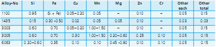
*Maximum, unless shown as a range
Alloys of 2xxx, 5xxx, 7xxx and 8xxx are not suitable for brazing with non-corrosive flux- es. The only exception is alloy 7072.
Step 2
Clean the SurfacesDust and dirt, condensates, lubricants and oils must be thoroughly removed. If the metal work pieces are poorly prepared, the flux will not spread evenly and the flow of filler alloy will be haphazard: it will either not spread properly or will discolour. The conse- quence would be an incomplete joint. The first step is therefore: always clean the components of all oil and grease. The surfaces can be cleaned using either chemical, water-based or thermal cleaning techniques and substances.
Aqueous CleaningAqueous or water based cleaning is a quite efficient and robust process, but still generates some waste water. Aqueous cleaning starts off with a concentrated metal cleaning agent, which is subsequently diluted with water to 1% to 5% (v/v). The composition of a supplier’s cleaning solution is proprietary, but usually contains a mixture of surfactants, detergents and active ingredients such as sodium carbonate that serves to elevate the pH. Once diluted, the cleaning solution will typically have an elevated pH in the range of pH 9 to 12. There are acid based solutions, but appear to be less common. The best water-based cleaners contain water, tensides, cleaning agent and active ingredients such as carbonates. The cleaning solution works best at higher temperatures and is usually recommended to operate at 50 °C to 80 °C. Cleaning action is quicker at higher solution temperatures.
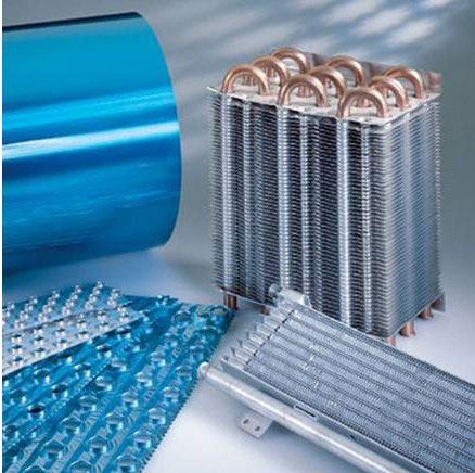
Thermal DegreasingThermal degreasing works by elevating the temperature of the work piece so that lubricants present on the surfaces will be evaporated. This procedure only works with special types of lubricants known as evaporative or vanishing oils. Vanishing oils are light duty lubricants used mostly for the fabrication of heat exchanger fins, although they are now finding uses in the stamping and forming of other heat exchanger components. Lubricants not designed for thermal degreasing must not be used. These could leave behind thermal decomposition products and carbonaceous residues which at higher level prevent brazing and have the potential to degrade product appearance and accelerate corrosion.
Step 3
Remove the Oxide LayerSuccessful aluminium bonding requires prior removal of the oxide layer. Flux in the molten stage partially dissolves and removes oxide layer from the metal surface. The metal surface is therefore cleaned by the flux itself, leaving the surface ideally prepared for the filler alloy to join the metal work pieces. Therefore it is of primary importance to provide flux to the brazed joints.
Step 4
Choose the Right Flux and the Right Filler AlloyWhen brazing with flux, a typical filler alloy is a fusible alloy of aluminium and silicon. There are many different filler alloys available: furnace brazing uses mainly filler alloys with 6.8 to 8.2 per cent Si (AA4343) and also 9 to 11 per cent Si (AA4045).
Step 5
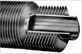
Select Capillary Size (Gap)Making a perfect joint requires the components to have the right capillary gap. Only if the gap is correct will the filler alloy spread when molten, by capillary action. Filler alloy, but not an excessive amount, must be available to fill the joint. It is necessary to have intimate contact between the two components to be joined and the filler metal at some point along the joint. A common phrase to emphasize this point is that “filler metal can run, but it cannot jump”. This contact point is what initiates the capillary flow of the filler metal.
A gap between the two components to be joined is necessary to
allow the molten flux to be drawn into and clean and dissolve the oxides and allow the filler metal to be drawn in freely and evenly. The size of the gap determines the strength of the capillary pull.
For Controlled Atmosphere Brazing (CAB), gap clearances of 0.10 mm to 0.15 mm are recommended for non-clad components (when the filler metal is fed externally. For clad components such as in a tube to header joint where the tube is clad, the clearance is provided by the thickness of the cladding layer and so intimate contact is recommended. Larger gap clearances reduce capillary action while smaller gaps may restrict filler metal flow causing discontinuities in the joint. Friction fits must be avoided with non-clad components.
Step 6
Apply Suffcient Amounts of FluxIn practice the recommended loading for fluxing is 5 g/m2, uniformly distributed on all active brazing surfaces. To visualize what 5 g/m2 flux loading might look like, think of a very dusty car. As the heat exchange manufacturer gains experience with his products, he may find that a little more is required for consistent brazing or that he can get away with a little less flux. Too little flux will result in poor filler metal flow, poor joint formation, higher reject rates, and inconsistent brazing. In other words, the process becomes very sensitive. Too much flux will not affect the brazing results. However there will be pooling of flux which can drip on the muffle floor, the surface of the brazed product will be gray and there will be visible signs of flux residue. Furthermore, flux will accumulate on fixtures more rapidly which then requires more frequent maintenance. More importantly yet, using too much flux will increase the process costs. The exact amount of filler alloy is also a crucial factor in furnace brazing: too much solder can result in the dissolution and erosion of the metal work pieces and reduced material thickness. This may in turn lead to leakage or reduced component life.
Step 7
Heat Metal Components EvenlyAchieving an even temperature distribution of 600°C throughout the work pieces is an important factor in controlled atmosphere brazing. Slow heating ensures even temperature distribution and a consistent bond. Caution: Heating too slowly can dry out the flux, which reduces its effectiveness. There must be sufficient molten flux present when the solder reaches its melting point. As a rule, the heating cycle should be as fast as possible to achieve stable temperature distribution. In industry, heating rates up to 45°C/min in the range of ambient to 500°C are not uncommon. One could say that the faster the heating the better. However, temperature uniformity across the heat exchanger must be maintained especially when approaching the maximum brazing temperature and this becomes increasingly more difficult with fast heating rates. During heat up, there may be quite a variation in temperature across the brazed product. The variation will tighten as the maximum temperature is reached. At brazing temperature it is recommended that the variation should not exceed ± 5°C. This can be difficult to maintain when larger units are processed which have differing mass areas within the product. The brazed product should not remain at the maximum brazing temperature for any longer than 3 to 5 minutes. The reason is that a phenomenon known as filler metal erosion begins to take place as soon as the filler metal becomes molten. And so the longer the filler metal remains molten, the more severe the erosion is. Severe erosion is also caused by excessive brazing peak temperature.
General Product Availability
| Core Alloys | Cladding Alloys |
| AA 3003 AA 3004 3003+ZN (1.5% & 2.5%) >X900 with no Mg x900 0.10 Mg x900 0.27 Mg x900 0.55 Mg Dvlp High Temperature / High Strengh for CAC |
AA 4343 4343 + Zn (1%) AA 4045 4045 + 0.20 Mg 4045 + Zn (1% & 2%) AA 4104 AA 4147 3003 + Zn (Coolant Side) AA 7072 (Coolant Side) High Strenght Anodic X397 (Coolant Side) |
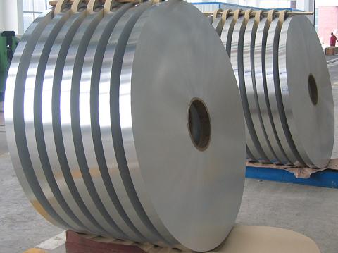
Gauge: 0.002" to 0.250" (0.051 mm to 6.35mm) Clad %: 2%-17% Widths: 0.5 inches to 63 inches (12 mm to 1600 mm)
| Series | Designation | Remark | |
| Clad alloy for brazing | CAB | 4343 4045 4047 | Used in controlled atmosphere brazing |
| VAC | 4104 4004 | Used in vacuum brazing | |
| Core alloy | Common alloy | 3003 3004 3005 | Good strength and corrosion resistance |
| Clad alloy for corrosion protection | 7072 1100 | Zn contained to protect core alloy | |
| Thickness(mm) | Width(mm) | Length(mm) | Temper |
| 0.03~0.2 | 4~1300 | C | O H12 H14 H16 H18 H19 H22 H24
H26 H28 |
| >0.2~3 | 4~1300 | C | |
| >3~6 | 16~1300 | ≤6500 | |
| >6~480 | ≤1300 | ≤6500 | |